

How To Draw Equipotential Lines
Learning Objectives
By the terminate of this section, yous will be able to:
- Explicate equipotential lines and equipotential surfaces.
- Describe the action of grounding an electrical appliance.
- Compare electric field and equipotential lines.
We can stand for electric potentials (voltages) pictorially, just as nosotros drew pictures to illustrate electric fields. Of course, the ii are related. Consider Figure ane, which shows an isolated positive point accuse and its electric field lines. Electric field lines radiate out from a positive charge and terminate on negative charges. While we use blue arrows to represent the magnitude and management of the electric field, we use green lines to represent places where the electric potential is constant. These are called equipotential lines in 2 dimensions, or equipotential surfaces in 3 dimensions. The term equipotential is also used as a noun, referring to an equipotential line or surface. The potential for a signal accuse is the same anywhere on an imaginary sphere of radius r surrounding the charge. This is true since the potential for a point accuse is given by
and, thus, has the aforementioned value at any bespeak that is a given distance r from the charge. An equipotential sphere is a circle in the ii-dimensional view of Effigy ane. Since the electric field lines point radially away from the charge, they are perpendicular to the equipotential lines.
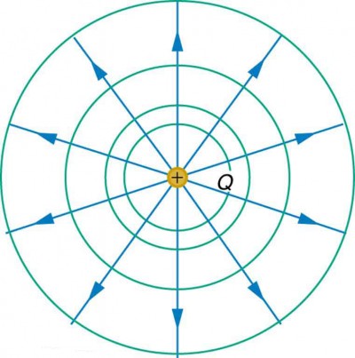 Figure i. An isolated point charge Q with its electrical field lines in blue and equipotential lines in light-green. The potential is the same along each equipotential line, meaning that no piece of work is required to movement a charge anywhere along one of those lines. Work is needed to move a charge from one equipotential line to some other. Equipotential lines are perpendicular to electrical field lines in every example.
It is of import to note that equipotential lines are always perpendicular to electric field lines . No work is required to move a charge forth an equipotential, since Δ5 = 0. Thus the work is
W = −ΔPE = −qΔ5 = 0.
Work is zero if force is perpendicular to movement. Force is in the same direction as E, so that motility forth an equipotential must be perpendicular to E. More precisely, work is related to the electric field by
W =Fd cosθ =qEd cosθ = 0.
Note that in the above equation, Eastward and F symbolize the magnitudes of the electric field strength and force, respectively. Neither q nor E nor d is zero, and so cosθ must be 0, meaning θ must be 90º. In other words, motion along an equipotential is perpendicular to Due east.
Ane of the rules for static electric fields and conductors is that the electric field must exist perpendicular to the surface of any conductor. This implies that a conductor is an equipotential surface in static situations. In that location can exist no voltage difference across the surface of a conductor, or charges will menses. One of the uses of this fact is that a conductor can exist fixed at zero volts by connecting information technology to the world with a good conductor—a process called grounding. Grounding can exist a useful safety tool. For example, grounding the metal case of an electric apparatus ensures that it is at nil volts relative to the globe.
Grounding
A usher can be fixed at zero volts by connecting information technology to the earth with a good conductor—a procedure called grounding.
Because a usher is an equipotential, information technology tin can replace any equipotential surface. For case, in Figure 1 a charged spherical conductor can replace the indicate charge, and the electric field and potential surfaces exterior of it will exist unchanged, confirming the contention that a spherical charge distribution is equivalent to a signal accuse at its center.
Figure 2 shows the electrical field and equipotential lines for two equal and opposite charges. Given the electric field lines, the equipotential lines tin can be fatigued simply by making them perpendicular to the electric field lines. Conversely, given the equipotential lines, as in Figure 3a, the electric field lines can be drawn by making them perpendicular to the equipotentials, every bit in Figure 3b.
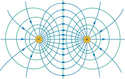 Figure 2. The electric field lines and equipotential lines for two equal just opposite charges. The equipotential lines can exist drawn by making them perpendicular to the electric field lines, if those are known. Note that the potential is greatest (most positive) near the positive charge and least (most negative) near the negative accuse.
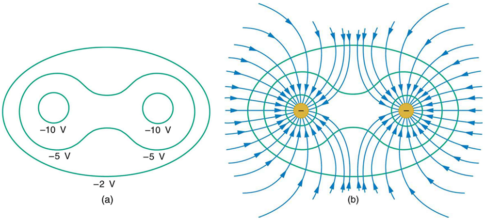 Figure iii. (a) These equipotential lines might exist measured with a voltmeter in a laboratory experiment. (b) The respective electric field lines are found by drawing them perpendicular to the equipotentials. Note that these fields are consistent with ii equal negative charges.
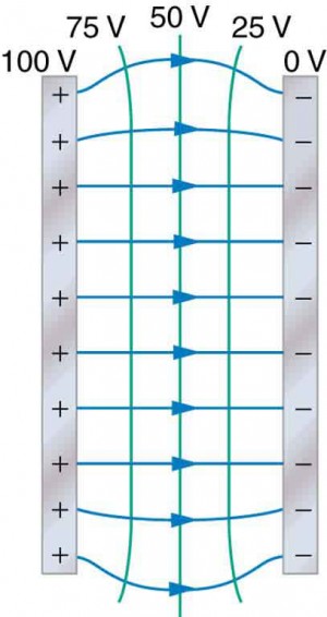 Effigy 4. The electric field and equipotential lines betwixt ii metal plates.
Ane of the most important cases is that of the familiar parallel conducting plates shown in Figure iv. Between the plates, the equipotentials are evenly spaced and parallel. The same field could exist maintained by placing conducting plates at the equipotential lines at the potentials shown.
An of import application of electric fields and equipotential lines involves the eye. The heart relies on electrical signals to maintain its rhythm. The movement of electric signals causes the chambers of the center to contract and relax. When a person has a eye attack, the motility of these electrical signals may be disturbed. An bogus pacemaker and a defibrillator can be used to initiate the rhythm of electric signals. The equipotential lines around the center, the thoracic region, and the axis of the eye are useful means of monitoring the construction and functions of the middle. An electrocardiogram (ECG) measures the pocket-sized electrical signals being generated during the activity of the center. More than about the relationship between electric fields and the heart is discussed in Energy Stored in Capacitors.
PhET Explorations: Charges and Fields
Motility point charges effectually on the playing field and then view the electric field, voltages, equipotential lines, and more than. It's colorful, it's dynamic, it's gratis.
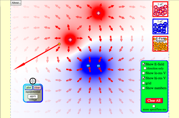 Click to run the simulation.
Section Summary
- An equipotential line is a line along which the electric potential is constant.
- An equipotential surface is a three-dimensional version of equipotential lines.
- Equipotential lines are always perpendicular to electric field lines.
- The process by which a conductor tin can be fixed at nada volts by connecting it to the earth with a good usher is called grounding.
Conceptual Questions
- What is an equipotential line? What is an equipotential surface?
- Explain in your own words why equipotential lines and surfaces must be perpendicular to electric field lines.
- Tin different equipotential lines cross? Explicate.
Problems & Exercises
- (a) Sketch the equipotential lines near a point charge +q. Indicate the direction of increasing potential. (b) Practise the same for a point charge −3q.
- Sketch the equipotential lines for the 2 equal positive charges shown in Figure five. Betoken the management of increasing potential.
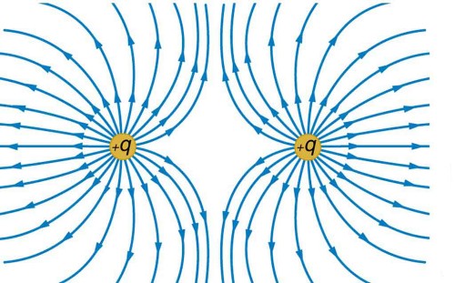 Figure five. The electric field near two equal positive charges is directed abroad from each of the charges.
 - Effigy half-dozen shows the electric field lines nigh two charges q 1 and q 2, the start having a magnitude four times that of the second. Sketch the equipotential lines for these ii charges, and betoken the direction of increasing potential.
- Sketch the equipotential lines a long altitude from the charges shown in Effigy 6. Indicate the management of increasing potential.
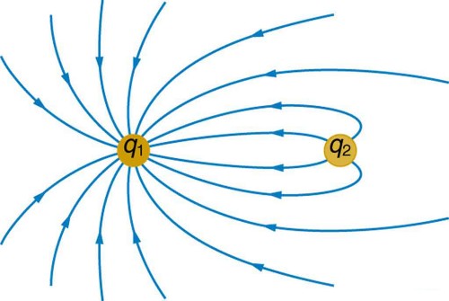 Figure vi. The electric field about two charges.
 - Sketch the equipotential lines in the vicinity of two opposite charges, where the negative charge is three times as great in magnitude as the positive. See Figure 6 for a like state of affairs. Indicate the management of increasing potential.
- Sketch the equipotential lines in the vicinity of the negatively charged usher in Effigy 7. How will these equipotentials expect a long distance from the object?
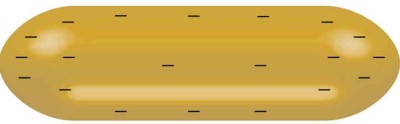 Effigy 7. A negatively charged conductor.
 - Sketch the equipotential lines surrounding the two conducting plates shown in Effigy viii, given the top plate is positive and the lesser plate has an equal corporeality of negative charge. Be certain to betoken the distribution of accuse on the plates. Is the field strongest where the plates are closest? Why should information technology be?
 Effigy 8.
 - (a) Sketch the electric field lines in the vicinity of the charged insulator in Figure 9. Note its non-uniform accuse distribution. (b) Sketch equipotential lines surrounding the insulator. Indicate the direction of increasing potential.
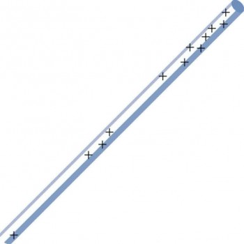 Figure 9. A charged insulating rod such as might be used in a classroom demonstration.
 - The naturally occurring accuse on the ground on a fine twenty-four hours out in the open country is –one.00 nC/10002. (a) What is the electric field relative to ground at a peak of iii.00 m? (b) Calculate the electrical potential at this acme. (c) Sketch electric field and equipotential lines for this scenario.
- The lesser electric ray (Narcine bancroftii) maintains an incredible accuse on its caput and a charge equal in magnitude simply opposite in sign on its tail (Effigy x). (a) Sketch the equipotential lines surrounding the ray. (b) Sketch the equipotentials when the ray is almost a send with a conducting surface. (c) How could this charge distribution be of use to the ray?
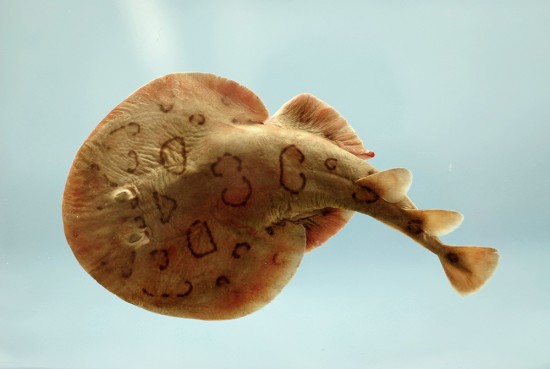 Figure 10. Bottom electrical ray (Narcine bancroftii) (credit: National Oceanic and Atmospheric Administration, NOAA's Fisheries Collection).
Glossary
equipotential line: a line forth which the electric potential is abiding
grounding: fixing a conductor at cipher volts by connecting it to the earth or ground
Licenses and Attributions

How To Draw Equipotential Lines,
Source: https://www.coursehero.com/study-guides/physics/19-4-equipotential-lines/
Posted by: murraynessittere.blogspot.com
0 Response to "How To Draw Equipotential Lines"
Post a Comment